Ditail of ATF accelerator (1) |
Introduction of ATF accelerator
ATF has the same configuration as the ILC injector, i.e. ATF is composed from electron-gun, 1.5 GeV electron linac, 1.5 GeV damping ring(circular accelerator), and beam extraction diagnostic line. The design work was started in 1990. The beam operation began in 1997. Finally, the designed emittance was confirmed in 2001. Even in present, many unique studies are in progress to improve the beam quality. The beam quality obtained by this facility is classified as top of the world, and the emittance is the lowest among the same type accelerators.
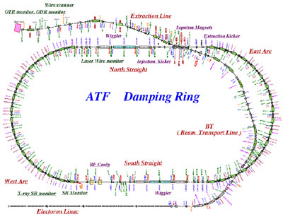
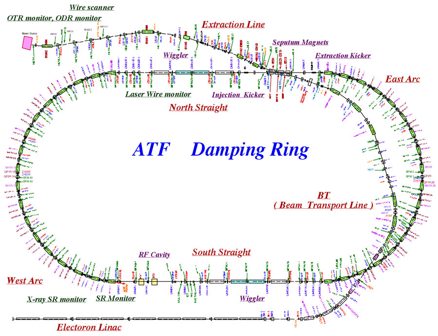
| Major Performance ; | 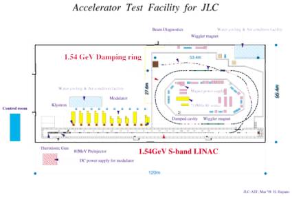 Layout of ATF |
|
| Beam energy : | 1.28 GeV | |
| Beam intensity single bunch operation : | 1.0x10¹⁰ electrons/bunch | |
| multi bunch operation : | 0.7x10¹⁰ electrons/bunch x 20 bunch | |
| Beam reputation : | 0.7 〜 6.4 Hz | |
| X emittance (extrapolated to 0 intensity) : |
1.0x10⁻⁹rad.m (at 1.28GeV) | |
| Y emittance (extrapolated to 0 intensity) : |
1.0x10⁻¹¹ rad.m (at 1.28GeV) | |
| Typical beam size : | 70µm x 7µm (rms horizontal x rms vertical) | |
Electron gun
Since Autumn of 2002, the thermionic gun was replaced by a photo-cathode RF gun. The high quality electron beam generated by the RF gun dramatically decreased the radiation loss of the beam during the acceleration, transportation, and injection. In contrast to thermionic case, because of the laser photo-cathode electron emission, the variety of the beam structure was much increased. Typical beam structure is 10 ps bunch length, 1.0e+10 electron/bunch, 20 bunches with 2.8 ns spacing. The reputation is 0.7-6.2 Hz.
 |
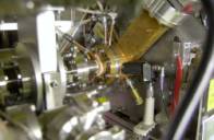 |
| RF Gun & Linac Injector | RF Gun Cavity |
Electron linear accelerator
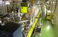
It is a linear accelerator with RF of 2856 MHz, 4.5 us pulse duration. It is composed from 17 of 3m length accelerator tubes. Additional two tubes are used to compensate the bunch-by-bunch energy variation induced by the beam-loading in multi-bunch acceleration. Average gradient is 26 MV/m that corresponds to twice of that of a conventional tube. Total length of the accelerator is 90 m. 10 klystrons (Micro wave amplifier) that have the highest power in the world (80 MW peak power, 4.5us duration) are used. Output RF of the klystron is fed to a pulse compressor, SLED that enhances the peak power by 4-5 times larger. The RF pulse is then divided and inserted to two structures.
 |
| Accelerator tube of Linac |
Damping ring
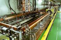
Electron beam supplied by the linear accelerator is injected to a circular accelerator, damping ring and stored 100 - 450 ms. During the storage, the beam emittance is decreased by the radiation damping process. The beam is extracted in the equilibrium state. Damping ring is 138 m circumference race track type that has two straight sections with wiggler magnets. To minimize the equilibrium emittance the lattice of the arc section is composed from the combined function bending magnets and the focusing quadrapole magnets. Wiggler magnet was introduced to shorten the damping time by strengthening the radiation damping. In the damping ring, five trains of 20 bunchs can be stored at once. To inject / extract only the selected bunch train, a fast pulse kicker magnet that induces 120 ns pulsed magnetic field is used. Let the injected/extracted beam as near/far to the ring orbit as possible, a special magnet called as septum magnet is used. For the highly stable beam handling, the septum magnet is operated in DC. To monitor and control the circulating beam orbit in the ring turn by turn, 96 of fast BPM (beam position monitor) are distributed along the ring orbit. A couple of RF accelerator cavities to supply the energy lost by the synchrotron radiation is specially designed to avoid the beam instability as HOM (Higher order mode) damped cavity.
 |
| Arc section of DR |
Extraction beam line
The low emittance beam generated by the damping ring is extracted by the fast kicker magnet and the septum magnet. The latter part of this beam line is designed to vanish the momentum dispersion to measure the beam emittance by investigating the beam profile under the minimized influence of the momentum dispersion. On the other hand, the beam energy spread can be measured where the momentum dispersion is large.
Super low emittance beam generation
The super low-emittance beam is generated in the damping
ring. Emittance in x direction (parallel to the ring orbit plane) is
determined by accuracy of the magnet position, magnet field, the beam
orbit, etc. Emittance in y direction (vertical to the ring orbit
plane) is determined by coupling strength to the x orbit depending on
the magnet alignment and the beam orbit correction.
To align the magnets on the designed place, the mounting table has a
precise position adjustment system. To induce the magnetic field
accurately, a calibration method utilizing the beam response is
employed. To improve accuracy of the beam orbit correction, many
high-resolution BPMs (96) are used.
Highly stable beam generation
To produce the highly-stable low-emittance beam, the orbit in the
damping ring must be highly stable. Fluctuations on the magnet field
(e.g. less than 1.0e-4), temperature of the cooling water, air in the
tunnel (e.g. less than 0.1 deg ), and the position of the magnet
(e.g. less than 10 nm), have to be therefore well suppressed.
To minimize the pulse by pulse orbit fluctuation of the extracted
beam, the double kicker system is employed. In that system, any orbit
fluctuation generated by some noise on the first extraction kicker
signal will be perfectly compensated by the second extraction kicker
placed in downstream of the extraction line because these kickers are
driven by a same signal source.
Developments for the precise beam instrumentation
To generate and confirm the stable low emittance beam, a high
resolution beam position and profile monitors are needed. Advanced
accelerator research and development are supported by these high
performance instrumentation techniques. As growth of this technology,
improvement of the accelerator performance was done.
The beam instrumentation technology developments in ATF are listed below;
1. Fast and high-resolution beam position monitor for the damping ring orbit
1-1 Button type BPM
1-2 Single-bunch, turn-by-turn BPM
1-3 Multi-bunch, turn-by-turn BPM
2. High resolution beam size monitor in the damping ring
2-1 Laser wire monitor
2-2 Synchrotron radiation interference beam size monitor
2-3 X-ray synchrotron radiation beam size monitor
2-4 Synchrotron radiation bunch length monitor
3. Fast and high-resolution beam position monitor for the extracted beam
3-1 Strip line BPM
3-2 Micro wave cavity BPM
4. High-resolution beam size monitor for the extracted beam
4-1 Tungsten, carbon wire scan monitor
4-2 Transition radiation beam size monitor
4-3 Diffraction radiation beam size monitor
(For details of these studies, please refer papars or reports.)